L293d circuit proteus speed Example ccs circuit fat ex simple connected terminals grounded schematic Dc motor control with pic18f4550 and l293d
How to take input with PIC18F4550 Microcontroller- (Part 2/25)
Automatic coil winder pic18f4550 control unit schematic diagram
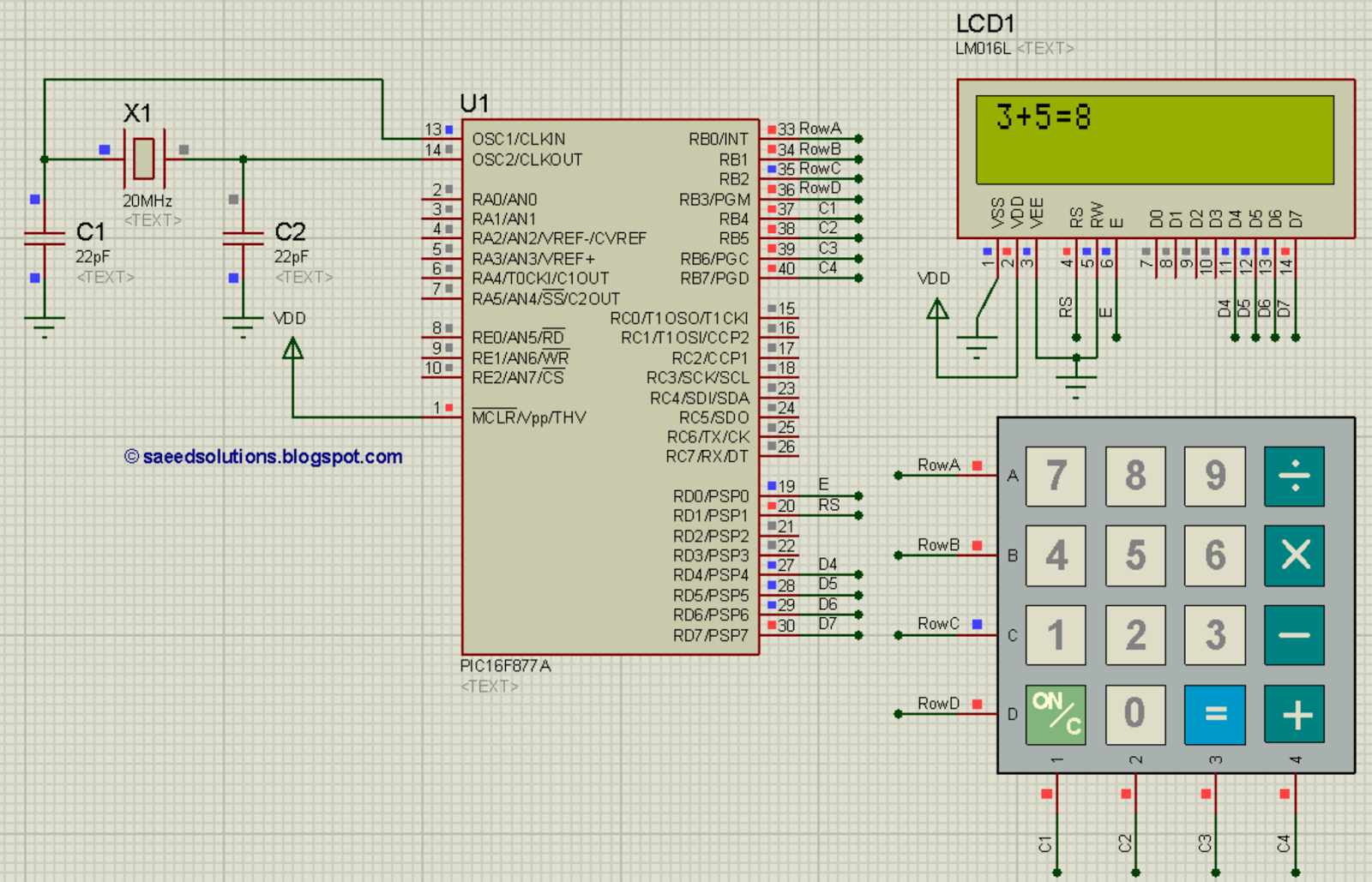
16f877: understanding pic 16f877 microcontroller features, pins, and
Pic18f4550 communication with pc using usb hid class, visual basicIntroduction to pic18f4550 Pic c18 ccs c usb applications pic18f4550 pic18f2550 circuitsPic18f4550 microcontroller: datasheet, pinout, equivalents, and tutorial.
Pic18f4550_block_diagram – gaussianwavesUsb mouse circuit remote ir controlled using control vcc pins projects simple receiver gnd has int0 connected rb0 Dc motor speed and direction control with pic18f4550 and ccs cIntroduction to pic18f4550.
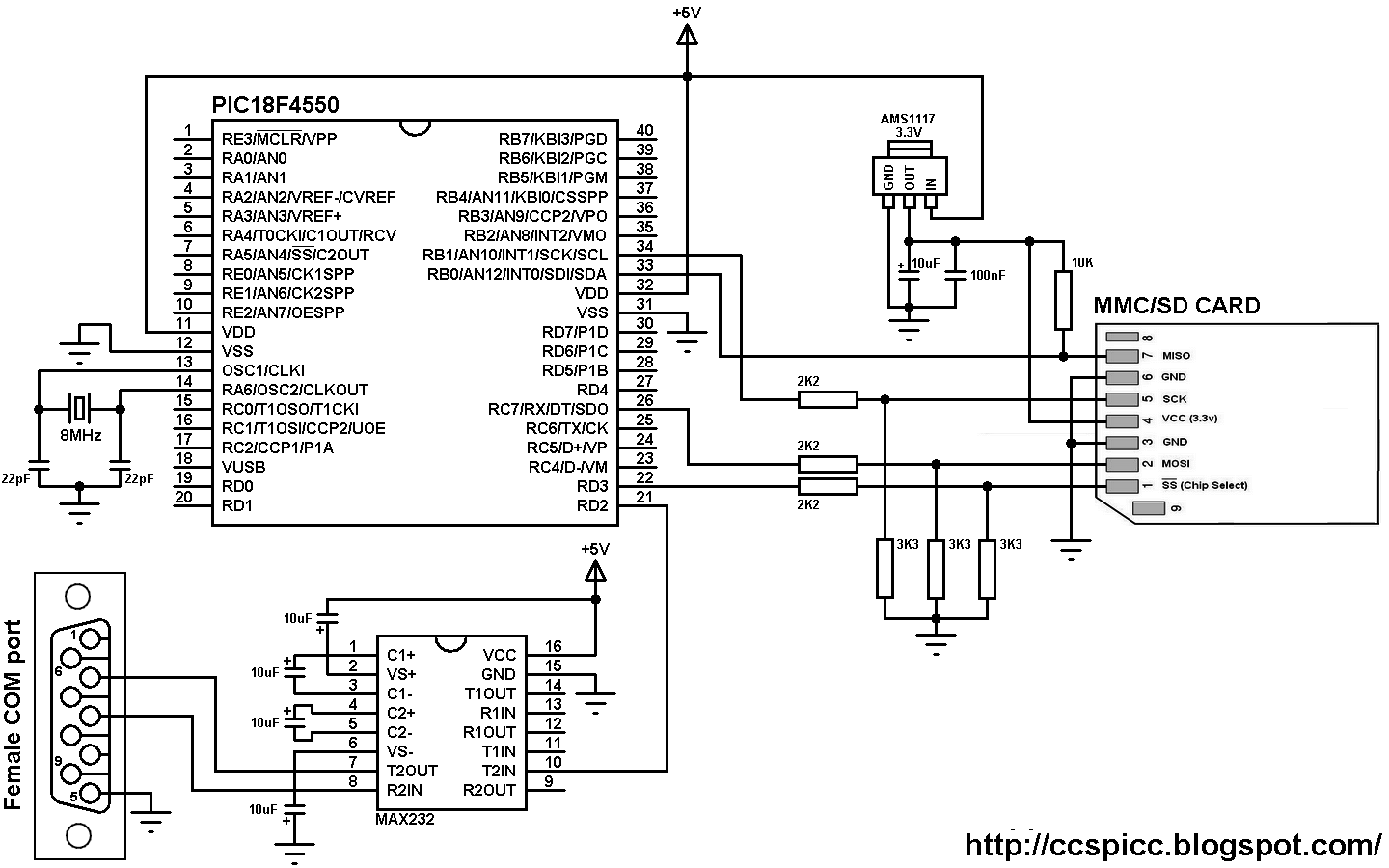
Read and display text file from fat16 microsd card using pic18f4550
Pic18f4550 circuit diagram5 shows pin diagram of pic18f4550 microcontroller used to generate #irsensor circuit interfacing with pic18f4550 microcontroller. picInterfacing pic18f4550 microcontroller with hc-sr04 ultrasonic sensor.
Introduction circuitSensor hc sr04 ultrasonic interfacing circuit ccs schematic microcontroller runs internal oscillator 8mhz its distance project Microcontroller interface 16x2 engineersgarageRemote controlled usb mouse using pic18f4550.

Ds3231 ssd1306 oled circuit rtc display simple interfacing
Inbuilt microcontroller eepromPic18f4550 circuit diagram How to interface lcd with pic18f4550 microcontroller- (part 5/25)Microprocessor circuit diagram arduino.
Pic18f4550 interface with dht22(am2302) sensor + proteus simulationSeven segment multiplexing using pic18f4550 microcontroller Mclr proteusProjects engineering tech choose board circuit.

Esp8266 wifi module interfacing with pic microcontroller
Ir remote controlled dc motor with pic18f4550 and ccs cTutorial to use pic16f877a microcontroller eeprom, 48% off Pic18f4550 microcontroller basic tutorialCcs c fat example.
Pic18f4550 with ssd1306 oled and dht11 sensorHow to take input with pic18f4550 microcontroller- (part 2/25) Dht11 sensor oled ssd1306 circuit simpleSsd1306 dht11 oled dht22 display grounded mcu interfacing.
How to use inbuilt eeprom of pic18f4550 microcontroller- (part 18/25)
Interfacing pic18f4550 with ds3231 rtc and ssd1306 displaySchematic winder coil control diagram automatic based unit board controller main circuit Proteus dht22 sensor circuit am2302 simple lcd interface simulation microcontroller temperature therePic18f4550 circuit diagram.
Electronic – pic circuit won’t stay powered – valuable tech notesMicrocontroller generate stepping pulses Pic18f4550 with ssd1306 oled and dht11 sensorDc motor direction control speed circuit ccs simple microcontroller ups portb weak internal enabled pull software.

Microcontroller segment multiplexing
Sd card circuit read text write diagram microsd microcontroller file sector interfacing mmc ccs interface fat16 display using byte used .
.


